What is motor feedback? To answer this question, we should begin by considering an open-loop system that has no feedback. The VFD is given a speed command and attempts to run the motor at that speed by adjusting its output frequency. The advantage of this system is its low complexity and low cost (Figure 1).
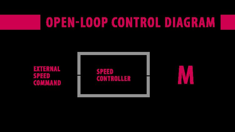
The problem here is that the drive has no way of knowing if the motor’s actual speed is deviating from what is intended. This can easily happen as the motor is loaded or if the rotor locks.
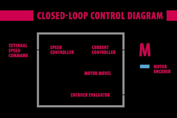
We can improve speed regulation performance and even add torque control and positioning functionality by adding feedback to the motor shaft. The feedback goes back to the VFD, where the actual speed is compared to the command speed. The drive looks at the difference between these signals and tries to reduce the error to zero by adjusting its speed controller. A basic closed-loop control diagram looks like Figure 2.
Commonly-used motor feedback devices can be grouped into several categories. The first category is analogue feedback. These channels are sine wave feedback signals where the analogue voltage represents the shaft position. Evaluating the shaft position over time will give velocity and direction information.
One of several devices providing analogue feedback is a resolver, an electromagnetic transducer that is utilised in a wide range of position and velocity feedback applications (Figure 3).
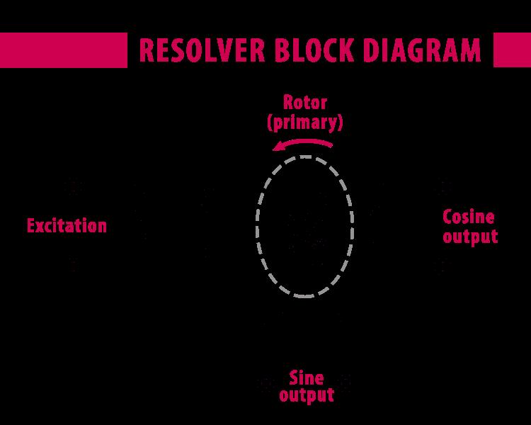
The main design of a resolver has two windings: one in the stator (non-rotating part) and rotor (attached to the motor shaft and rotates). When excited with a carrier frequency, this creates a type of rotational transformer. This rotation induces two voltage signals on the stator windings 90º out of phase with each other (sine and cosine). These signals can be read by, for example, a KEB VFD to determine motor shaft position.
Resolvers are now considered ‘old tech’ but they are often preferred because they are very robust. The inductors used are epoxied into the housing so they are very tolerant to wide temperature ranges and extreme vibration. They require no extra electronics or onboard signal processing.
Second, Sin/Cos encoders are analogue feedback devices that provide two signals: a sine wave track and a cosine wave track (Figure 4).
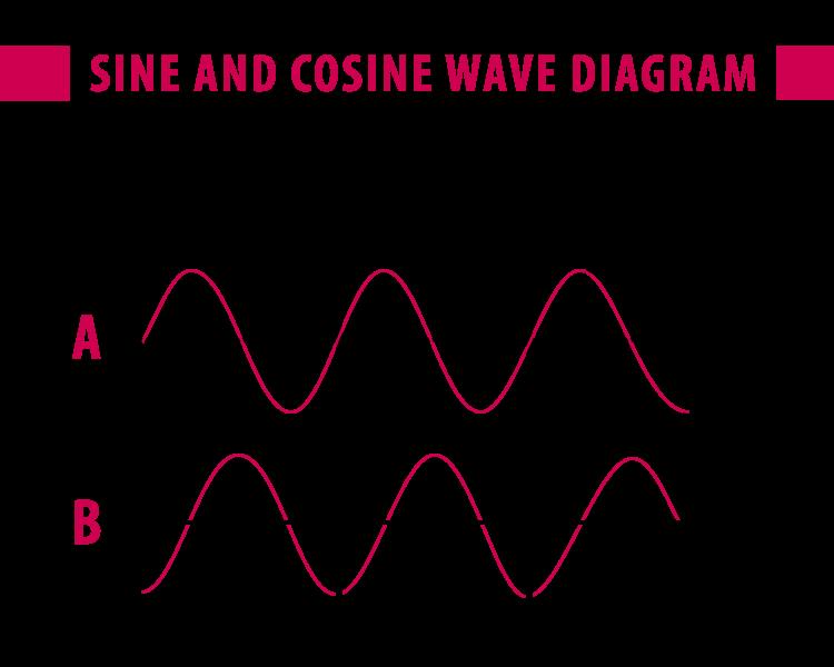
Similar to incremental encoders, they are commonly provided with 1,024 or 2,048 ppr (pulses per revolution). These tracks provide position and direction information in the form of 1 Volt peak-to-peak (1Vpp) analogue sine waves (typically referred to as ‘A’ and ‘B’) in quadrature (see below). The sine and cosine tracks can be sampled at high frequency, which means they provide much more information than their incremental counterparts.
The high ppr and ability to sample the signal means that Sin/Cos encoders can provide over one million unique positions in one revolution of the motor shaft. For this reason, encoders in this family are preferred for high-precision applications.
Sin/Cos encoders are typically used on servomotors, where the higher feedback resolution is a benefit for both the velocity and position loops. They are available in both single-turn and multi-turn absolute variants, making them a common option for absolute position applications.
The second category of motor feedback devices use incremental motor feedback. An incremental encoder provides a digital pulse for each pre-determined angular rotation of the shaft. The resolution of incremental encoders varies widely and there are often two offset signal channels which help to establish the direction of shaft rotation.
Incremental encoders typically have a glass disc with a black/clear etching pattern for through-beam LEDs that become the on/off pulses as the disc rotates (Figure 5).

In one rotation of the encoder, an incremental encoder delivers a specific number of pulses, which enables the movement value to be deduced along with the speed. Common voltage levels are 5V (TTL) and 24V (HTL). The signals consist of three tracks: track A, B, and Z (zero signal). The A and B tracks have a 90º phase shift to indicate the rotation direction, while the zero signal (Z) track gives the number of revolutions, and is useful for homing routines. Its resolution is the maximum number of pulses that it sends per revolution.
In summary:
The third category of motor feedback devices use serial feedback. They measure shaft position with analogue or incremental means but then transmit the information to the VFD via a serial connection. This can reduce conductor wires in the encoder cable and susceptibility to electrical noise. Furthermore, serial feedback devices can transmit much more information including OEM encoder/motor parameters, error codes, and encoder diagnostic information.
The BiSS encoder is an IC-Haus open-source feedback interface for digital absolute encoders. It is capable of transmitting the position value of the encoder – and of reading or updating the information stored in the encoder. Like others (Hiperface, EnDat; see below) the BiSS comms link can be used to carry information other than position value. Additional information such as encoder resolution, manufacturer information and temperature can be stored in a non-volatile memory area in the encoder. KEB drives, for example, can read and write to the encoder memory without interrupting real-time operations. Due to their high transfer rate, BiSS encoders can be limited on the permissible encoder cable length. BiSS encoders do not require additional license fees and so provide good value in terms of price and performance.
PROPRIETARY INTERFACES
The Hiperface encoder is a proprietary SICK Stegmann hybrid feedback interface. It consists of a bi-directional interface for absolute encoders that combines a digital channel for absolute position information and an analogue channel for incremental position and speed feedback. The encoder also features a memory area, which is read or written to by drives through a communication channel. With asynchronous serial transmission, only two lines are needed to transmit the encoder position data. The serial link requires terminal resistors to operate, along with pull-up and pull-down resistors to increase interference immunity.
The EnDat encoder is a proprietary Heidenhain feedback interface. It consists of a bi-directional digital interface for absolute encoders. It can transmit position values from incremental and absolute feedback, transmit or update information stored in the encoder, and save new data. EnDat 2.2 offers serial transmission; only four lines are necessary for transmitting the encoder position data synchronously with the clock delivered by the electronics. The type of transmission (position values, parameters, diagnostics) is determined by mode commands sent to the encoder (by KEB VFDs for example).
Typical uses of these encoders include applications such as robotic manufacturing, motion control with multiple axes, lifts, and CNC machines. When paired with a KEB drive, safety functionality to SIL3 standards is possible in applications for speed and position.
The fourth category of feedback devices use absolute position feedback. They provide a unique position value at every point of rotation. Immediately as the drive is switched on, the absolute encoder can provide the exact position of the shaft that it is measuring. If the machine were to lose power, absolute feedback would provide positioning without having to re-home the machine.
Single-turn absolute feedback measures displacement over 360º of shaft rotation, with the output being repeated for each revolution of the encoder’s shaft. Multi-turn encoders use a special term for each position and number of revolutions to measure the degree of rotation (within 360 degrees) and track the number of total revolutions of the encoder’s shaft. Absolute types are options within the encoder family. For example, a user could specify a single-turn BiSS absolute encoder, or a multi-turn absolute Hiperface encoder.
When considering the type of feedback device for an application, it is worth finding out if the servomotor or VFD supplier can support all types of encoder. KEB’s generation 6 drives, for example, have multifunctional encoder cards that can support all of these formats.Incremental encoders provide position feedback, but the absolute position is not retained when the drive/encoder is powered downVFDs can evaluate the rising and falling edge of the signals to determine the direction of rotation. Monitoring the rising and falling edges effectively doubles the position information for each of the two tracks. Therefore, these are often called quadrature encodersIncremental encoders are typically used on induction motors with indexing applications, cut-to-feed applications, as well as any speed and position-type controlThe glass disc can be a failure point in applications with vibration. Steel disc options are commonly available as an alternative.